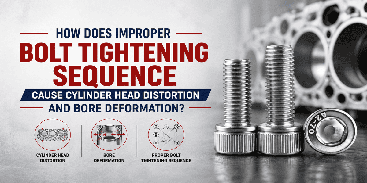
Как неправильная последовательность затяжки болтов вызывает деформацию головки блока цилиндров и деформацию отверстия?
Краткий ответ:
Неправильный порядок затяжки болтов может привести к тому, что одна часть головки блока цилиндров будет нагружена до того, как другие будут зажаты равномерно. Такая сила может вызвать деформацию самой головки, изменить коэффициент сжатия прокладки и привести к деформации гильзы цилиндра.
Таким образом, болты головки блока цилиндров затягиваются в определенном порядке, начиная с центра головки. Это делается постепенно, позволяя головке и прокладке равномерно осесть на блоке двигателя. Однако, в зависимости от двигателя, количества и расположения болтов, используемых прокладок и типа крепежа, процедура будет отличаться. При выполнении такой задачи всегда следует учитывать рекомендации производителя. CNRL производит крепеж для двигателей и других автомобильных применений. Компания была основана в 1996 году и имеет производственное помещение площадью 33 000 квадратных метров.
Почему важна последовательность затяжки?
Головка блока цилиндров реагирует на силу, создаваемую каждым крепежным элементом. Если болты в одной области затягиваются первыми, этот участок может сильно зажиматься, в то время как другие области остаются ослабленными. Правильная последовательность затяжки болтов постепенно распределяет силу, помогая головке равномерно прилегать к прокладке и блоку.
Деформация головки блока цилиндров
Несоответствие силы зажима может вызвать изгиб или скручивание головки блока цилиндров. Это может привести к неравномерному давлению на прокладки вокруг камеры сгорания, каналов охлаждения и масляных каналов.
Деформация гильзы цилиндра
Сила зажима также может передаваться на блок двигателя, влияя на распределение напряжений вдоль гильз цилиндров. Неравномерная нагрузка может привести к небольшой деформации гильз цилиндров.
Как порядок затяжки болтов распределяет силу зажима?
Каждый затянутый болт немного растягивается и создает силу зажима через соединение. Порядок затяжки болтов головки контролирует, как эта сила распределяется по головке блока цилиндров. Начиная с центра и двигаясь наружу, головка постепенно садится. Затягивание внешних или соседних болтов первым может ограничить одну секцию до того, как остальная часть головки будет должным образом зажата.
Постепенное нагружение
Болты головки цилиндров часто нагружаются в несколько циклов. Это связано с тем, что первый цикл предназначен для посадки цилиндра и прокладки, в то время как последующие циклы постепенно нагружают болты в той же последовательности.
Таким образом, гарантируется, что ни один болт не достигнет требуемой нагрузки до того, как другие болты станут тугими. Некоторые двигатели могут также иметь требования к угловой нагрузке.
Какие стандартные схемы затяжки болтов используются?
Ни одна схема затяжки болтов не подходит для каждого механического соединения. Расположение болтов и геометрия компонента определяют, как должна распределяться нагрузка. Тем не менее, спиральные, перекрестные и звездообразные схемы иллюстрируют основной принцип контролируемой затяжки.
Спиральная схема
В спиральной схеме процесс начинается с центра, а затем постепенно продолжается наружу. Это хорошо работает для многих конфигураций головок блока цилиндров, поскольку обеспечивает равномерное распределение давления затяжки изнутри наружу, не оставляя неравномерного давления ни в центре, ни по краям. Числа будут варьироваться в зависимости от используемого двигателя.
Перекрестная схема
В перекрестной схеме происходит чередование с одной стороны соединения с другой. В отличие от случая, когда соседние крепежные элементы затягиваются последовательно, в этом случае порядок пересекает деталь. Некоторые головки блока цилиндров используют порядок пересечения от центра наружу вместо истинной геометрической перекрестной схемы.
Звездообразная схема
Звездообразная схема повторяется по круговому или симметричному соединению. Она часто ассоциируется с такими компонентами, как фланцы и колесные сборки. Принцип заключается в сбалансированной нагрузке, но общая звездообразная схема не должна автоматически использоваться на головке блока цилиндров.
Приоритет отдается процедуре затяжки болтов двигателя, специфичной для конкретного двигателя, поскольку головки блока цилиндров различаются по форме, расположению болтов и структурной жесткости.
Как выглядит последовательность затяжки болтов головки блока цилиндров?
Рассмотрим головку блока цилиндров с десятью основными болтами. Вместо того чтобы начинать с одного конца и двигаться прямо поперек, процедура часто начинается с крепежных элементов, расположенных ближе к центру. Затем последовательность затяжки болтов головки блока цилиндров прогрессирует к обоим концам в контролируемом порядке.
Например, первая пара может располагаться вокруг центральных цилиндров. Последующие болты постепенно расширяют зону зажима к передней и задней части головки. Этот пример объясняет принцип, а не предоставляет универсальную последовательность. Правильная нумерация должна соответствовать спецификации производителя двигателя.
Многократные проходы затяжки
Тот же порядок может повторяться в течение нескольких этапов. Это дает соединению время осесть по мере увеличения силы зажима. Это также уменьшает разницу между сильно нагруженными и слабо нагруженными областями во время сборки.
Конкретные значения крутящего момента намеренно исключены здесь. Эти значения зависят от конструкции болта, конструкции двигателя, состояния резьбы, смазки и процедуры производителя.
Поэтому спецификацию автомобильной процедуры затяжки следует рассматривать вместе с требуемыми этапами крутящего момента или угла.
Какие ошибки могут привести к отказу прокладки?
Проблемы с прокладкой редко возникают из-за одного фактора. Состояние поверхности, состояние крепежа, установка и температура двигателя — все это может способствовать. Однако несколько ошибок при затяжке могут создать неравномерную силу зажима с момента сборки двигателя.
Начиная снаружи
Затягивание внешних болтов перед центральными может слишком рано ограничить концы головки блока цилиндров. Затем центр должен осесть на участках, которые уже сильно зажаты. Это может увеличить нежелательные изгибающие напряжения.
Приложение окончательной нагрузки за один проход
Доведение отдельных болтов до конечного состояния затяжки создает концентрированные нагрузки. Поэтапная затяжка распределяет возрастающую силу зажима по всей сборке. Это дает головке и прокладке более контролируемый путь к их конечному зажатому состоянию.
Использование неправильного порядка затяжки
Последовательность затяжки, которая работает для одного двигателя, может не работать для другого. Правильный порядок затяжки болтов головки блока цилиндров зависит от расположения болтов, геометрии головки, конструкции прокладки и конструкции двигателя. Общая схема должна только объяснять принцип, а не заменять сервисную информацию.
Игнорирование состояния резьбы и болтов
Трение резьбы влияет на то, как входное усилие затяжки превращается в натяжение болта. Грязные резьбы, поврежденные резьбы, покрытия и смазка могут изменить это соотношение. Поэтому состояние крепежа имеет значение наряду с последовательностью затяжки болтов головки блока цилиндров. Правильный порядок не может компенсировать поврежденные или неподходящие болты.
Как CNRL поддерживает точную затяжку болтов двигателя?
Указанная процедура затяжки предполагает, что крепеж соответствует своим предполагаемым размерам и механическим требованиям.
CNRL производит автомобильные болты, шпильки, винты, орехи, и сопутствующие крепежные компоненты. Его автомобильные крепежные изделия используются в системах двигателя, шасси, трансмиссии, тормозов и других системах автомобиля.
Ассортимент продукции компании включает крепежные изделия классов прочности от 4.8 до 12.9. Доступные продукты охватывают диаметры от 3 до 30 мм и длины от 6 до 300 мм.
Индивидуальные крепежи также могут быть произведены в соответствии с чертежами и требованиями применения.
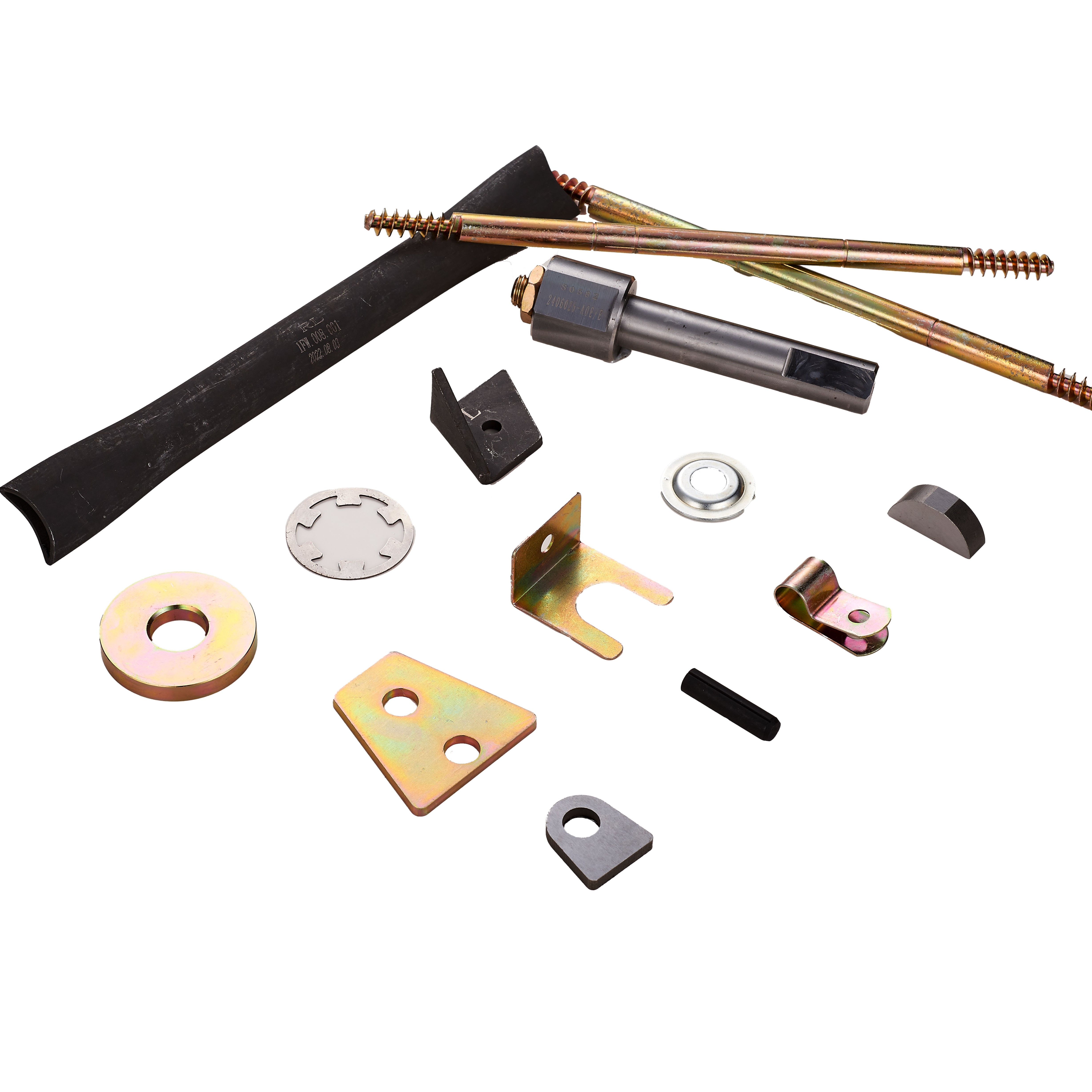
Автомобильные крепежные детали для двигателей Втулка Шайба Болты
ПодробнееДля применений в головке блока цилиндров материал болта, размеры, резьбы, термообработка, состояние поверхности и требования к затяжке должны работать вместе. Затем последовательность затяжки болтов помогает распределить результирующее усилие зажима по всей сборке.
Связаться с CNRL для комплектов болтов двигателя и спецификаций затяжки для конкретных применений.
CNRL — ваш надежный поставщик крепежных изделий.
Резьбовые вставки из нержавеющей стали для ремонта резьбы
Получить предложение